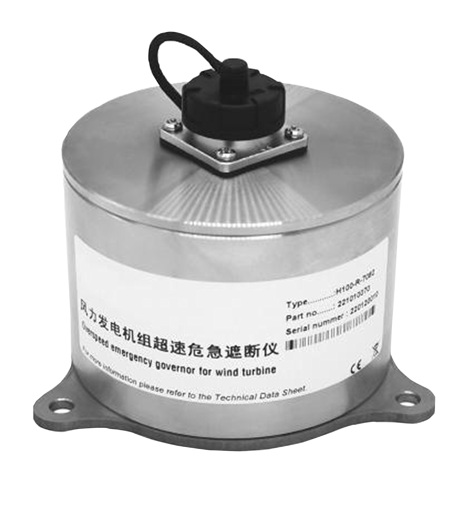
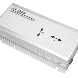
H100 Series Overspeed Crisis Interrupter Overspeed Emergency Governor Functional Features ● Used as speed monitoring and overspeed protection for fan impeller ● “The last straw” after fan overspeed ● Real-time monitoring timely control ● Easy installation and simple operation ● Military quality: anti-corrosion, anti-immersion, high temperature resistance, impact resistance Product Introduction H100 series fan overspeed emergency governor adopts high-quality anti-corrosion material coating on the outside and high-temperature resistant insulation material on the inside. It has the characteristics of anti-corrosion, waterproof, high temperature resistance, impact resistance, etc. The device is used for speed monitoring and overspeed protection of fan impeller. It monitors whether the speed exceeds the set warning value, and can monitor and protect the safe operation of the fan impeller in real time to prevent the fan from running away due to overspeed. It is the “last straw” after the fan overspeed. The overspeed emergency governor monitors the impeller speed in real time through the magnetoelectric sensor installed inside the device. The enhanced series also has the function of monitoring the vibration of the transmission chain, the inclination of the tower, the angle of the blades and other parameters. The alarm parameters and alarm delay can be set by the user according to different models and environments. When a fault occurs, the fault site can be digitally protected to provide data support for later fault detection and analysis. It has the characteristics of a “black box” for wind turbines. There is a zero-potential relay output port in the alarm circuit. The alarm signal can control a remote alarm system or be used to shut down a monitoring process. The H100 series overspeed emergency trip device is designed with a variety of communication interfaces (such as CAN, RS485, etc.), which can be applied to different wind turbines and can be installed and periodically maintained by computer. For more product information, please refer to the relevant parameters below. Wiring method
|
Line number
|
Function
|
color
|
Logo
|
illustrate
|
|
1
|
power supply+
|
red
|
24V DC
|
power supply+
|
|
2
|
power supply-
|
blue
|
GND
|
power supply-
|
|
3
|
System self-test output
|
purple
|
System OK
|
24V Level
|
|
4
|
RS485-A
|
black
|
A
|
Communications
|
|
5
|
RS485-B
|
grey
|
B
|
Communications
|
|
6
|
Relay output – normally open
|
white
|
NO
|
Overspeed control and propeller retraction shutdown
|
|
7
|
Relay output – normally closed
|
Green
|
NC
|
Overspeed control and propeller retraction shutdown
|
|
8
|
Relay-common
|
Yellow Green
|
COM
|
Public Port
|
|
9
|
CAN-H
|
Light blue
|
Can_H
|
Communications
|
|
10
|
CAN-L
|
orange
|
Can_L
|
Communications
|
|
11
|
Signal Input 1
|
Brown
|
T_in1
|
test
|
|
12
|
Signal Input 2
|
pink
|
T_in2
|
Technical Parameters
|
Related Features
|
Minimum
|
typical
|
maximum
|
unit
|
|
Supply voltage(DC)
|
18
|
24
|
30
|
V
|
|
Current consumption
|
—
|
30
|
50
|
mA
|
|
power
|
—
|
0.8
|
1.2
|
W
|
|
input
|
—
|
2
|
—
|
road
|
|
output
|
—
|
1
|
—
|
road
|
|
Communication Ports
|
—
|
2
|
—
|
road
|
|
Tilt monitoring range
|
-90
|
—
|
90
|
°
|
|
Speed monitoring range
|
0.01
|
—
|
333.33
|
rpm
|
|
Tilt resolution
|
—
|
0.01
|
—
|
°
|
|
Speed resolution
|
—
|
0.01
|
—
|
rpm
|
|
Operating temperature
|
-55
|
—
|
125
|
℃
|
|
Maximum allowable humidity(40℃时)
|
—
|
100%
|
—
|
—
|
|
Heavy pressure resistance
|
—
|
5000
|
—
|
pound
|
|
Drop resistance
|
—
|
150
|
—
|
m
|
|
Shock resistance
|
—
|
500
|
—
|
g
|
|
High temperature resistance (260℃ for 10 hours or 1100℃ for 1 hour)
|
260
|
—
|
1100
|
℃
|
|
Maximum operating altitude
|
—
|
5000
|
—
|
m
|

